Robotic Spider Platform

V2 Actuator and Power Testbench

A staged V2 prototype focused on actuator packaging, gear and bearing layouts, power-distribution testing, and motor-control wiring before full-body assembly.

Active prototype Actuator Testing Power Distribution Motor Control 3D Printed Parts Gear Layout Bench Testing
V2 Actuator and Power Testbench
V2 actuator testbench
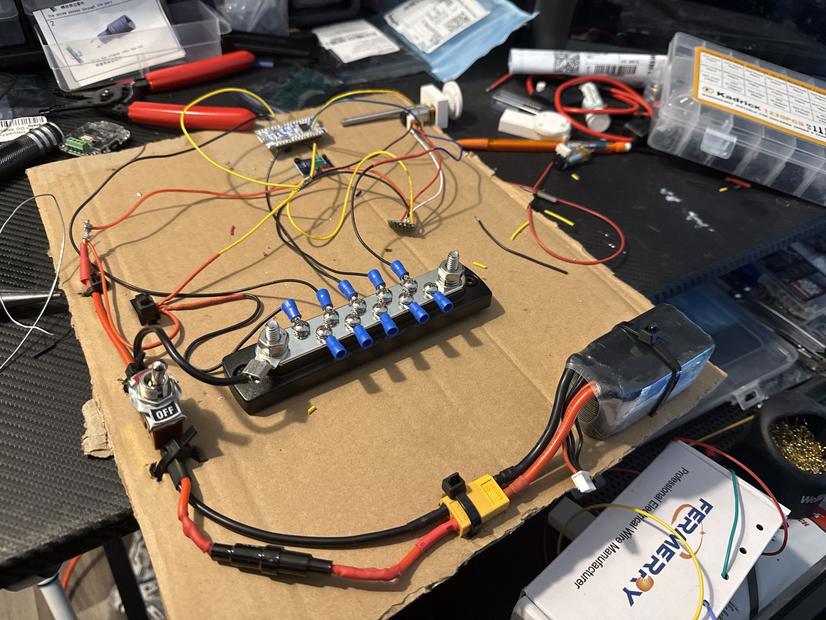
Power distribution bench
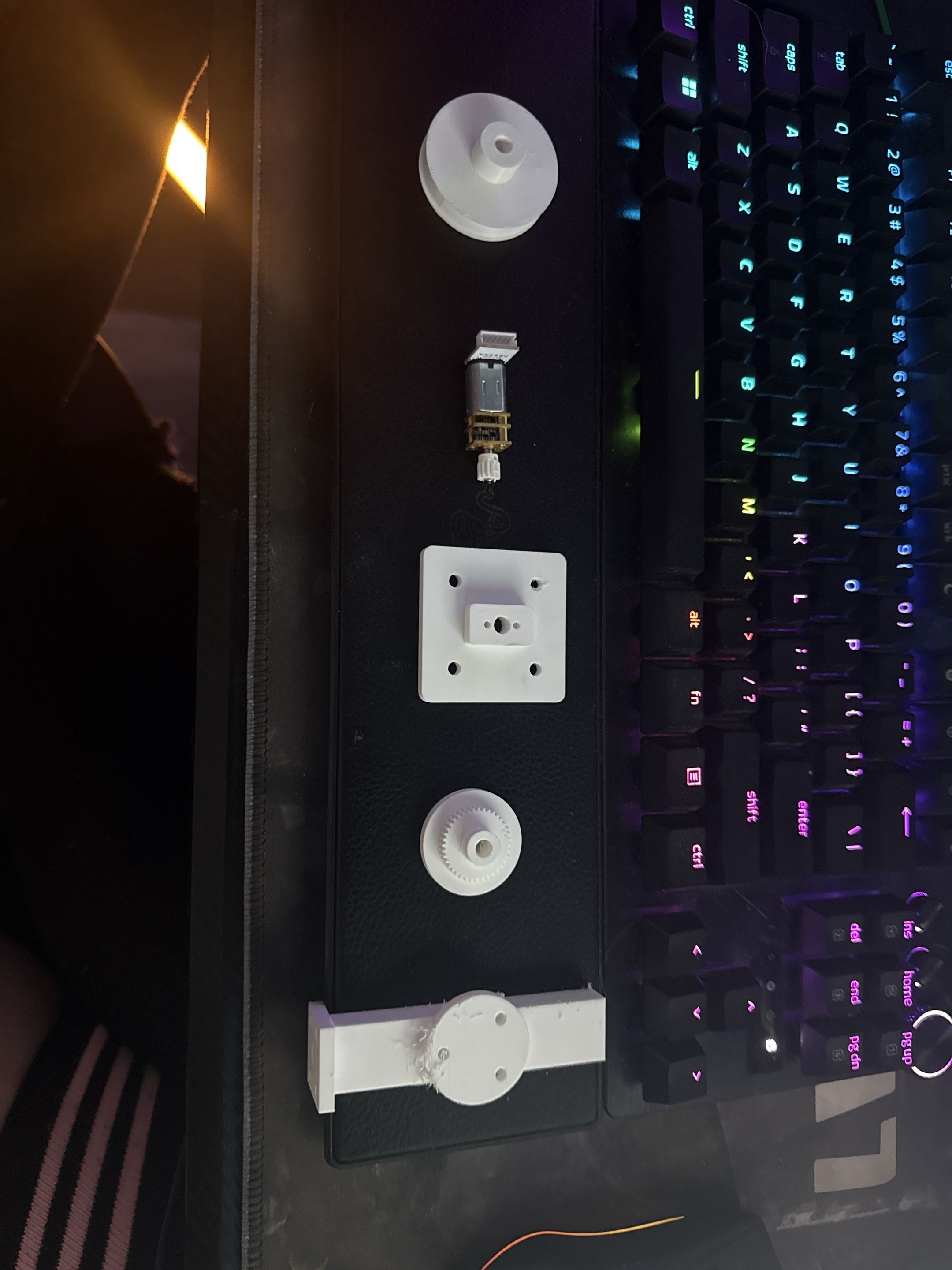
Printed joint components
Gear and bearing layout tested

Overview

Profile Summary

V2 is the main mechanical and electrical test stage for the spider platform. It focuses on proving pieces of the leg and power system before scaling into a complete 8-legged robot.

What I built

V2 is a staged prototype focused on actuator packaging, gear and bearing layouts, power-distribution testing, motor-control wiring, and leg-joint mechanics before committing to a full robot body.

Why I built it

The goal is to prove the hard physical systems before scaling. A full 8-leg robot would multiply every mistake across many joints, so V2 isolates the actuator, power, and mechanical packaging problems first.

System

Core Hardware

Mechanical V2 focus Printed actuator mounts, bearings, shafts, gears, and leg-joint packaging
Power testbench LiPo battery, XT connector, inline switch, bus bar, and distributed wiring
Motor-control testing Small DC gear motors and motor-driver test wiring
Current direction Single repeatable leg module before full-body scaling

Build process

What I Personally Did

Built a V2 electrical testbench for battery power, switching, power distribution, and actuator wiring
Used a bus-bar style distribution layout to organize power routing for multiple future actuator loads
Printed and test-fit actuator mounts, gear components, bearing plates, shafts, and leg-joint pieces
Explored compact gear and bearing layouts for a cleaner mechanical joint design
Tested early small DC gear-motor concepts as an alternative to simple hobby-servo actuation
Investigated how actuator placement affects leg bulk, torque path, and maintainability

Problems I ran into

A motor or servo can work on a bench but still fail as a robot part if it makes the leg too bulky, too weak, too heavy, or mechanically awkward.

A full 8-leg, 4-DOF-per-leg robot would create a large actuator count, so power distribution has to be designed early.

One printed joint or bracket is not enough; the design has to become repeatable across many joints without turning into a wiring and maintenance mess.

A single central controller becomes less attractive as actuator count increases, which is why the project direction favors modular leg control and staged subsystem validation.
What worked

  • • V2 created a clearer separation between power, actuator, mechanical, and control experiments
  • • The power bench gave the project a more realistic path for testing actuator loads
  • • Printed parts helped expose real packaging constraints instead of leaving the design as only a concept
  • • Gear and bearing experiments created a better basis for future joint design
  • • The project direction became more honest: prove one subsystem at a time, then scale

Remaining work

  • • Final single-leg mechanical module
  • • Confirmed actuator choice for the current leg design
  • • Validated torque and range of motion under load
  • • Final motor-driver and feedback-control layout
  • • Encoder feedback integration
  • • Repeatable wiring layout for one complete leg
  • • Clean modular leg-controller architecture

Takeaway

What I Learned

V2 made the project more grounded. The strongest next step is not building the full frame. It is proving one repeatable leg module with usable actuation, clean power routing, reliable control, and a mechanical layout that can actually scale.

Evidence

Project Evidence

Project photos grouped by build phase so older process documentation and newer standardized photos can coexist without weakening the presentation.

Project Evidence

Project photos showing build process, testing, troubleshooting, and historical context.

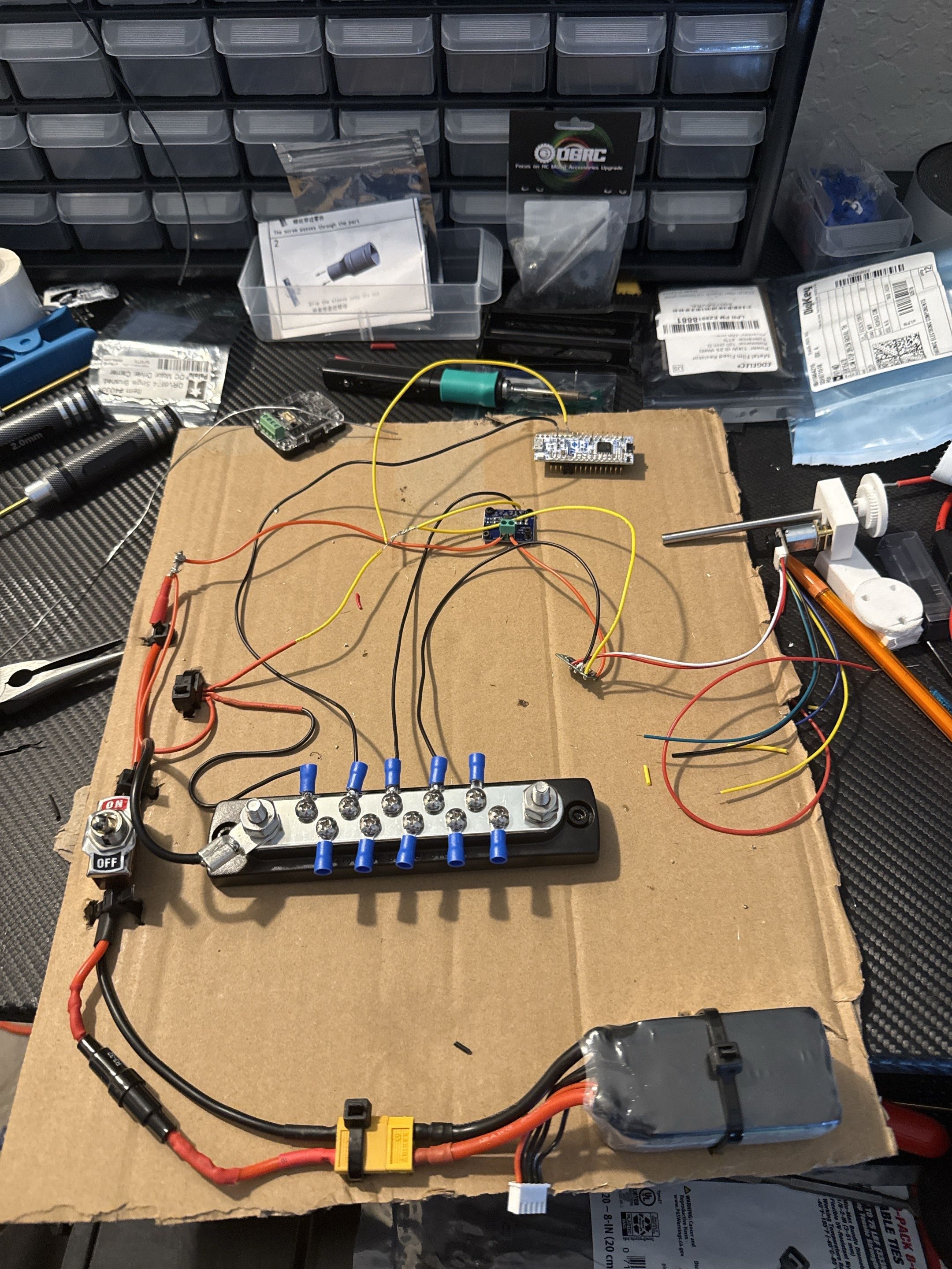
Robotic spider V2 power and actuator testbench with battery, wiring, and motor-control components.

V2 power and actuator testbench

Early V2 bench layout for battery power, switching, distribution, motor-driver wiring, and actuator testing before committing to a full leg assembly.

Build evidence

Angled view of the robotic spider V2 LiPo battery, XT connector, switch, bus bars, and temporary wiring.

Power-distribution layout

Angled view of the LiPo battery, XT connector, inline switch, bus-bar distribution, and temporary wiring used to test the power architecture.

Build evidence

3D-printed robotic spider joint parts laid out with a small gearmotor, bearing plate, shaft, and gear pieces.

Printed joint components

Printed parts, small gearmotor, bearing plate, shaft, and gear pieces laid out during the mechanical packaging stage.

Build evidence

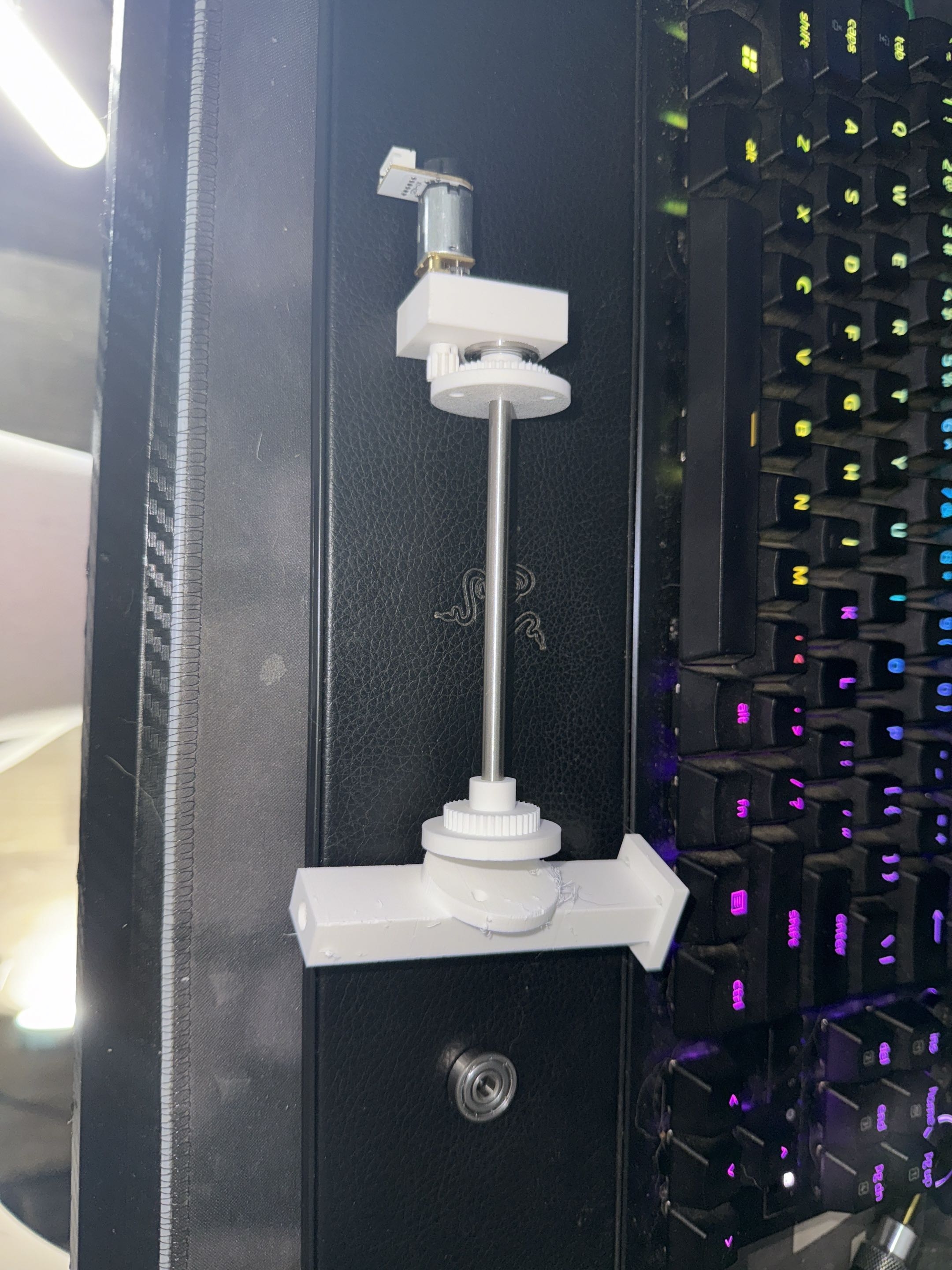
Prototype robotic spider actuator and joint assembly with DC gearmotor, printed mounts, shaft, gears, and bearing support.

Actuator and joint assembly

Prototype actuator/joint assembly using a small DC gearmotor, printed mounts, shaft, gear components, and bearing support.

Build evidence

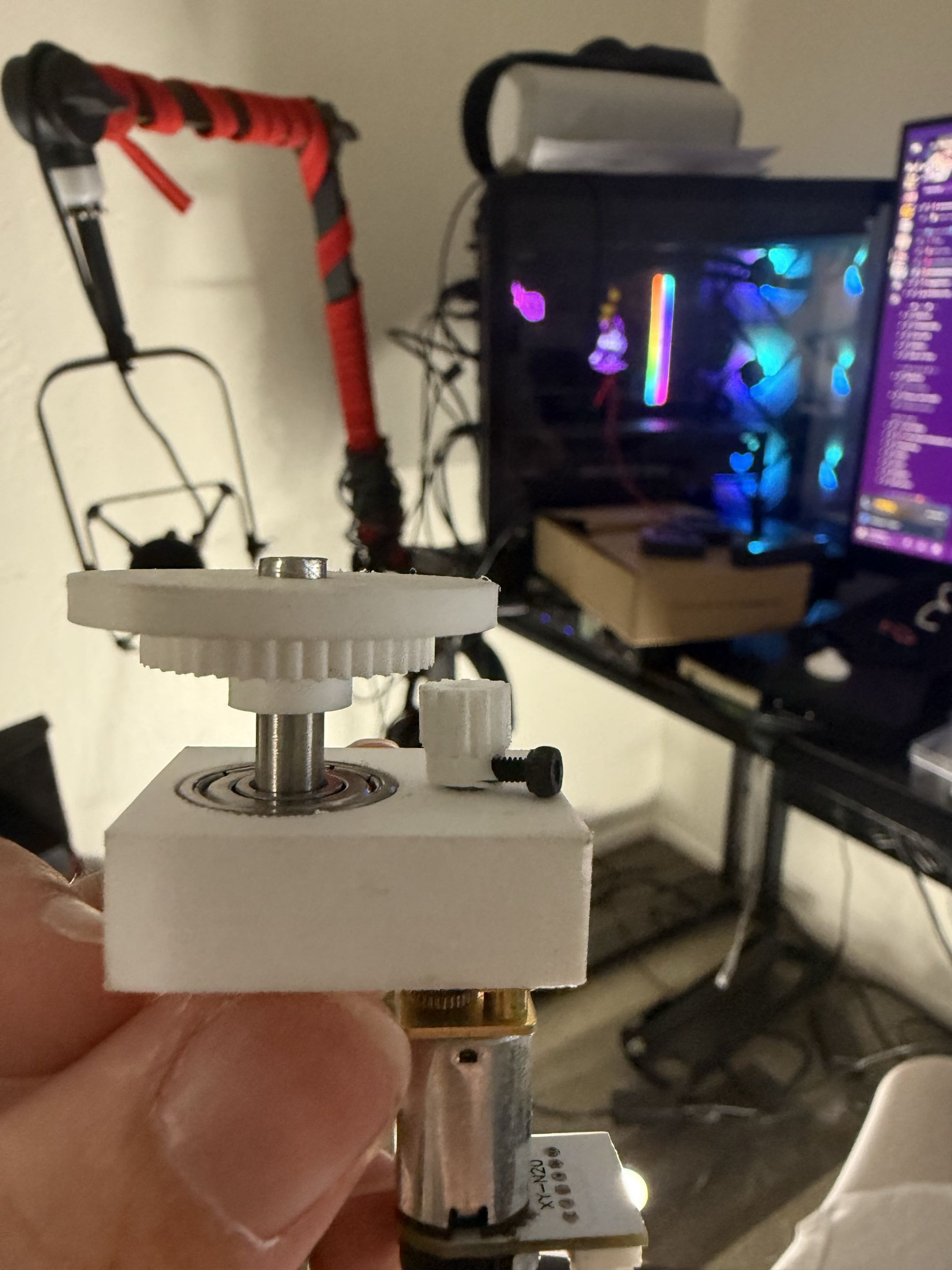
Close-up of a printed gear and bearing layout for the robotic spider joint mechanism.

Gear and bearing close-up

Close-up of the printed gear and bearing layout used to evaluate compact joint packaging and mechanical fit.

Build evidence

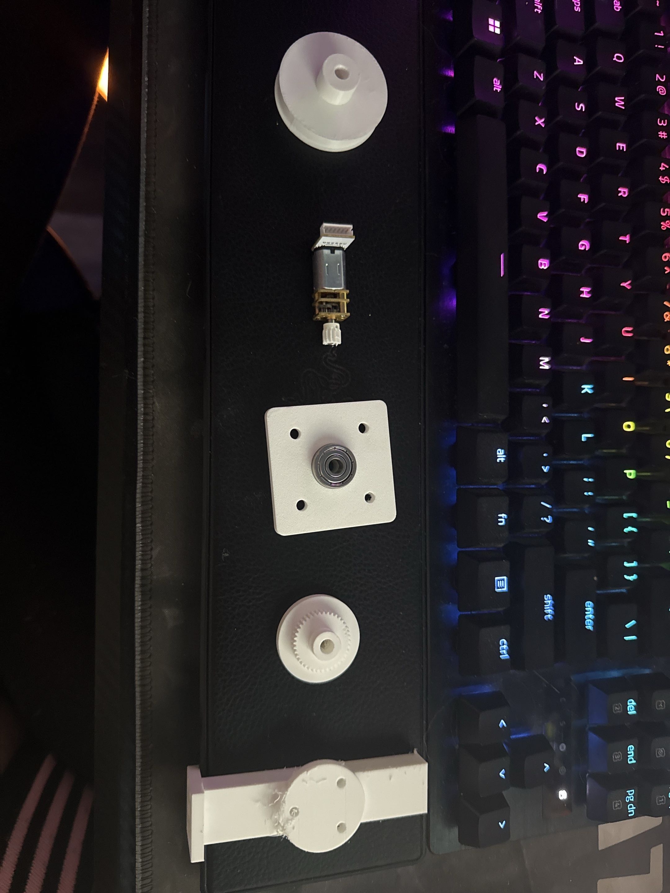
Flat layout of the robotic spider bearing plate, gear, motor, and printed joint pieces before assembly.

Bearing and gear layout

Flat layout showing the bearing plate, gear, motor, and printed leg/joint pieces before full assembly.

Build evidence

Back to Robotic Spider Platform All work