Problems I ran into
The project has too many subsystems to document cleanly on one page.
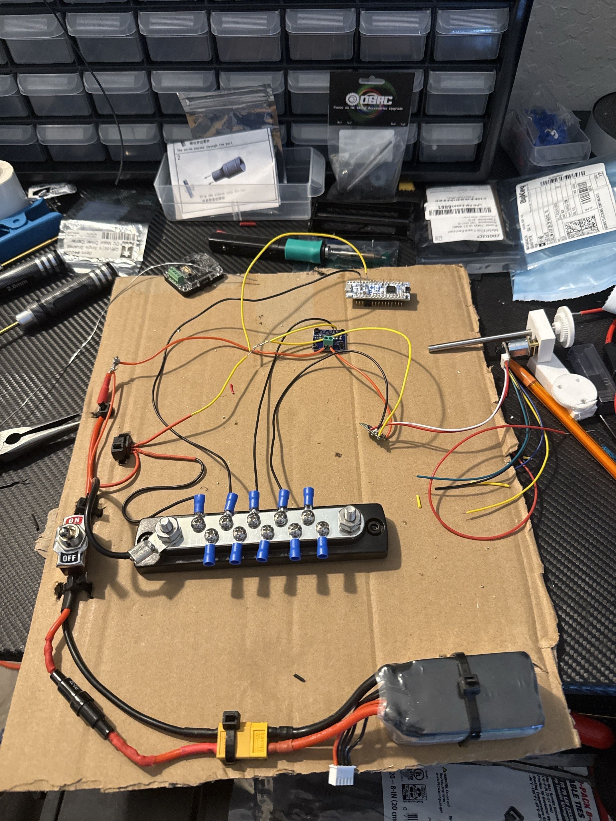
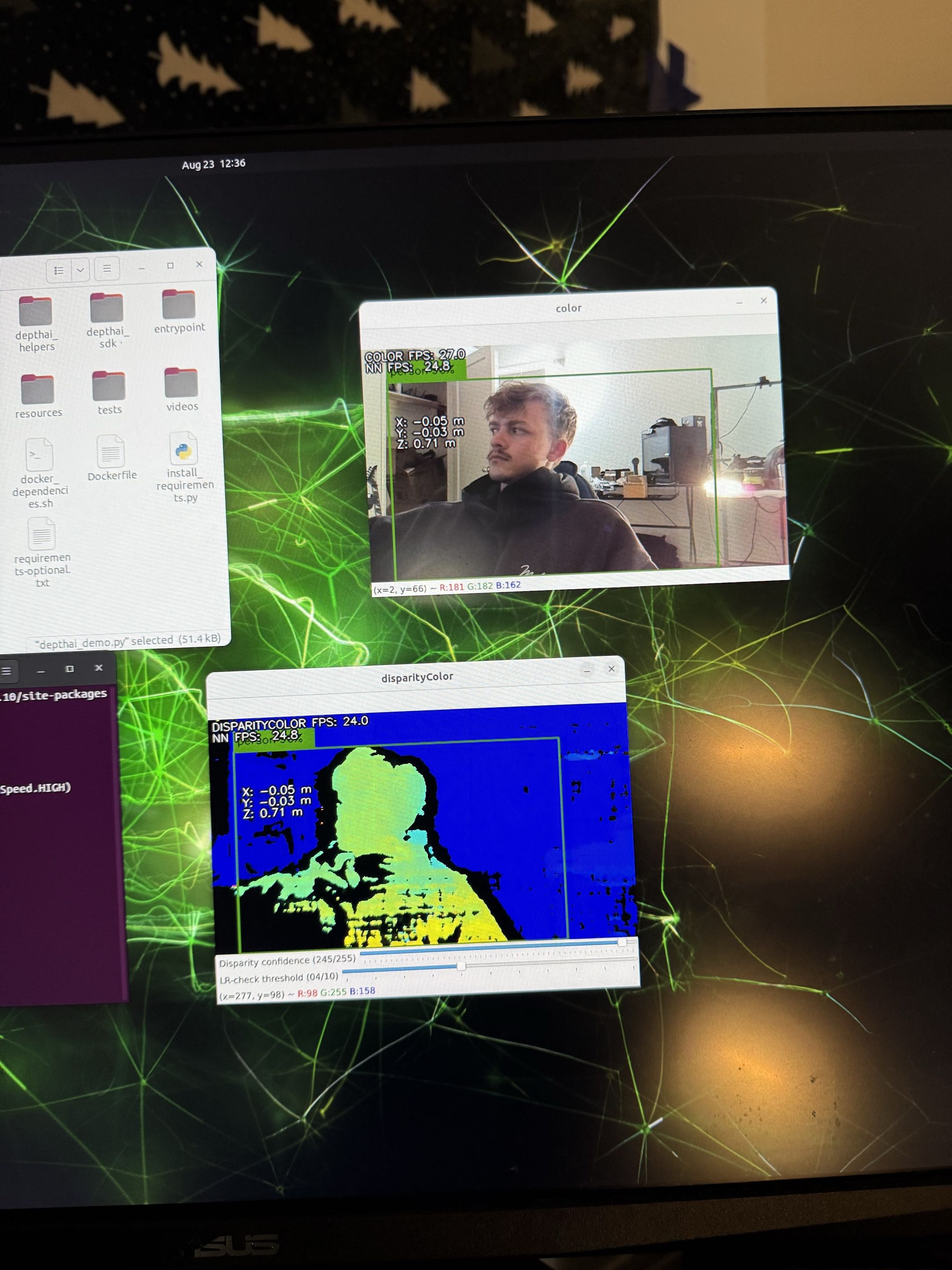
Actuator packaging, power distribution, control architecture, perception, and thermal handling each need their own documentation path.
The long-term goal includes autonomy, but the current bottlenecks are still mechanical repeatability, actuator selection, wiring, and subsystem validation.