Embedded Hardware

Remote Safe Retrofit

Retrofitted a small electronic safe with an ESP32-controlled solenoid latch, MOSFET load switching, flyback protection, HTTP control, and OTA firmware updates.

Functional Prototype ESP32 Solenoid Control MOSFET Switching Flyback Protection OTA Updates Embedded Retrofit
Remote Safe Retrofit
ESP32 control path
Solenoid latch actuation
MOSFET-switched load
Flyback diode protection
HTTP command interface
ArduinoOTA firmware updates

Overview

Project Summary

This project turned a basic electronic safe into a compact actuator-control retrofit. The useful part was not the safe itself; it was learning how to control a physical latch with a microcontroller, switch a solenoid safely, protect the circuit from the inductive load, and keep the firmware updateable after installation.

What I built

I replaced the safe's original control behavior with a custom ESP32-based control path. The ESP32 sends a logic signal to a MOSFET gate, the MOSFET switches the solenoid load, and the solenoid drives the latch. I added flyback protection across the solenoid and used gate-control resistors so the MOSFET had a defined state instead of floating during boot or reset.

Why I built it

The goal was to get practical reps with a real physical load instead of only working with LEDs or breadboard logic. A solenoid latch creates problems that matter in real embedded work: current draw, inductive kickback, switching behavior, default states, packaging, and wiring mistakes.

System

Core Hardware

Controller ESP32-based microcontroller
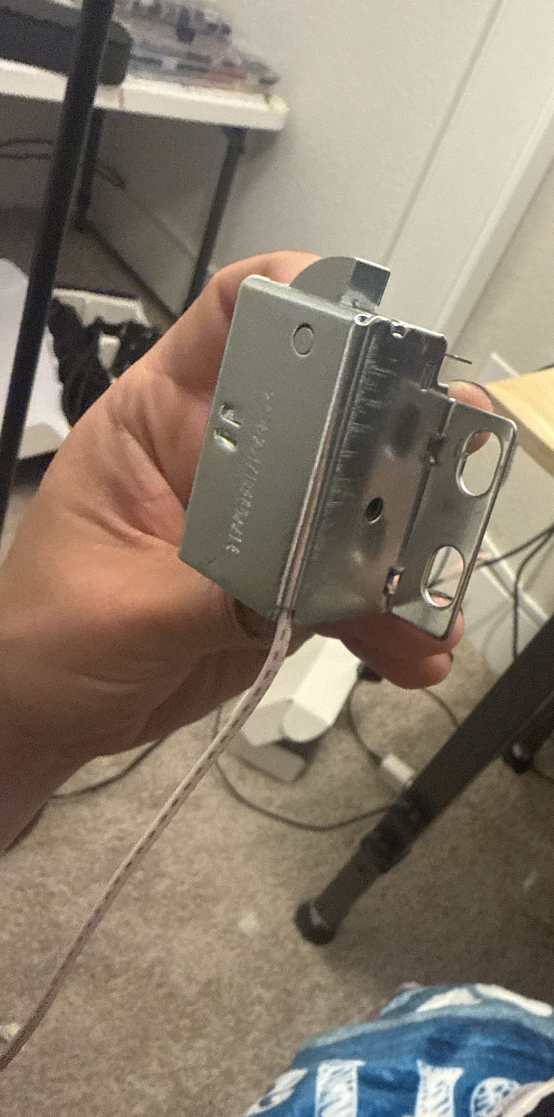
Actuator Low-voltage solenoid latch mechanism
Switching Logic-controlled MOSFET circuit
Protection Flyback diode across the solenoid load
Gate control Series gate resistor and pull-down resistor for predictable switching
Firmware HTTP command handling and ArduinoOTA update support

Build process

What I Personally Did

Opened the safe and reduced the system to its actual mechanical requirement: actuating the latch reliably.
Built the ESP32-to-MOSFET-to-solenoid control path so the microcontroller only handled logic-level control.
Added flyback diode protection across the solenoid to reduce voltage spikes when the coil de-energizes.
Used gate-control components so the MOSFET would not float or switch unpredictably during startup/reset states.
Added HTTP-based remote control behavior for triggering the latch over the network.
Added ArduinoOTA support so firmware could be updated without repeatedly opening the safe or reconnecting a programmer.
Debugged damaged or questionable circuit behavior after shorts/component issues and rechecked the MOSFET wiring, diode orientation, and power path.

Problems I ran into

The solenoid could not be treated like a simple low-voltage logic device. It is an inductive load, so the switching circuit needed protection.

The MOSFET gate needed a defined default state. A floating gate could make the latch behavior unreliable or unsafe.

The wiring had to fit around the safe's existing latch hardware, which made routing, strain relief, and serviceability harder than a bench-only prototype.

A short or wiring mistake damaged part of the control path, forcing a more careful review of the MOSFET, diode orientation, and power wiring.

Wireless control inside a metal safe is not ideal. The enclosure can weaken Wi-Fi, so this version should be treated as a learning prototype, not a finished commercial lock design.
What worked

  • • The safe became remotely controllable through a custom embedded control path.
  • • The solenoid was switched through a MOSFET instead of being driven directly from the microcontroller.
  • • Flyback protection and gate-control components moved the circuit closer to a real actuator-control design.
  • • OTA support made firmware changes easier after the electronics were installed.
  • • The project exposed real failure modes: shorts, inductive loads, switching behavior, packaging limits, and network-control tradeoffs.

Remaining work

  • • Add a cleaner internal mounting plate or enclosure for the control electronics.
  • • Add a physical service mode or local override so access does not depend only on network control.
  • • Add status feedback for latch state, power state, and command success/failure.
  • • Improve wiring strain relief and internal cable routing.
  • • Document the final circuit as a proper schematic instead of relying only on build notes.
  • • Evaluate external antenna placement or a different communication path if the metal enclosure weakens Wi-Fi too much.

Takeaway

What I Learned

The main lesson was the gap between controlling a logic signal and controlling a physical mechanism. A solenoid needs current handling, switching protection, defined default states, and careful wiring. The useful part of the project was not just making the safe open remotely; it was debugging the actuator-control path until the circuit behavior made sense.

Media

Functional test

Short test showing the safe mechanism actuating through the custom ESP32, MOSFET, and solenoid control path.

Evidence

Project Evidence

Project photos grouped by build phase so older process documentation and newer standardized photos can coexist without weakening the presentation.

Project Evidence

Project photos showing build process, testing, troubleshooting, and historical context.

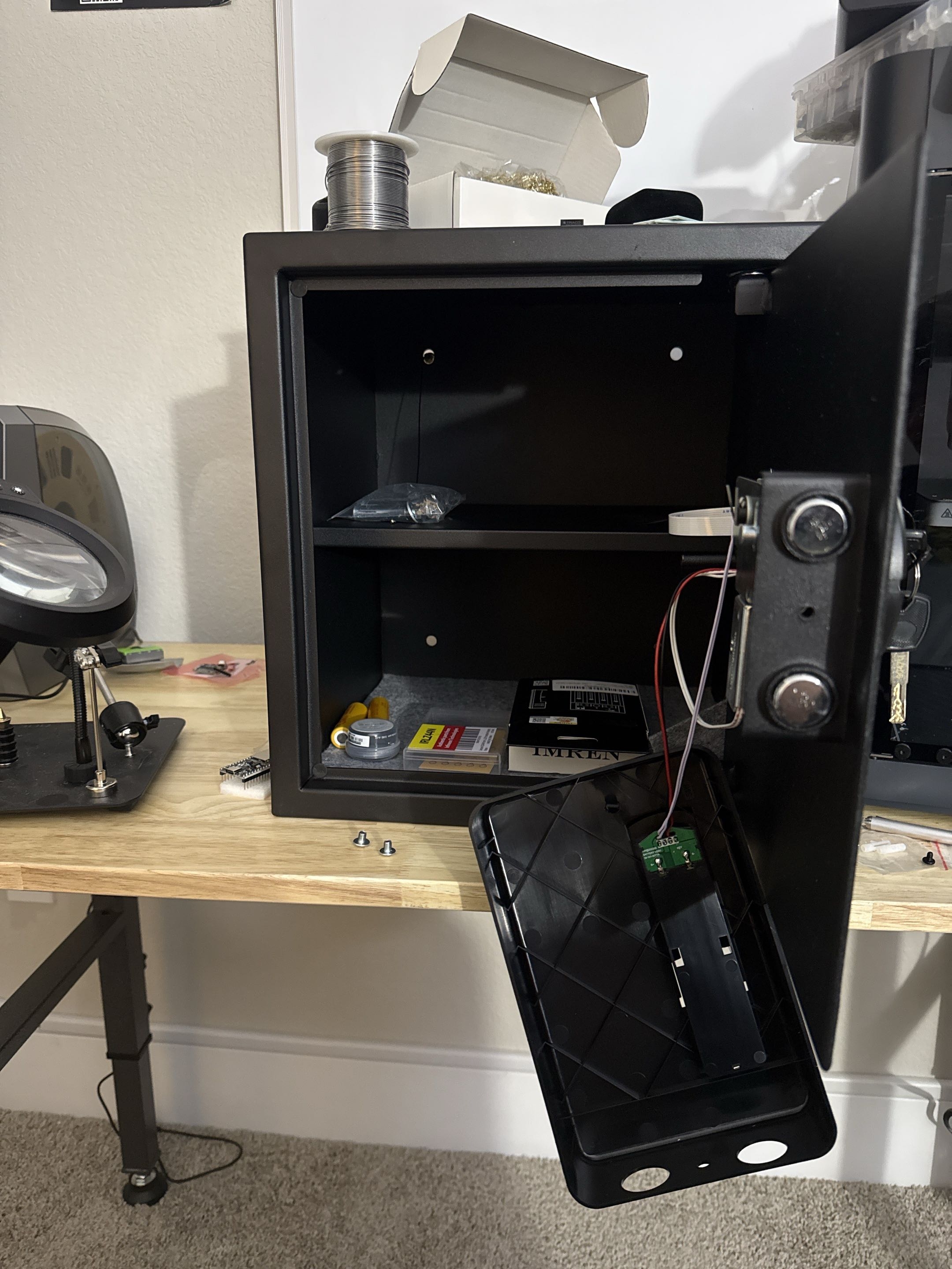
Safe opened for retrofit

Safe opened for retrofit

The safe opened up during the retrofit. This shows the existing door hardware, internal access, and latch area before the electronics were cleaned up into a final layout.

Build evidence

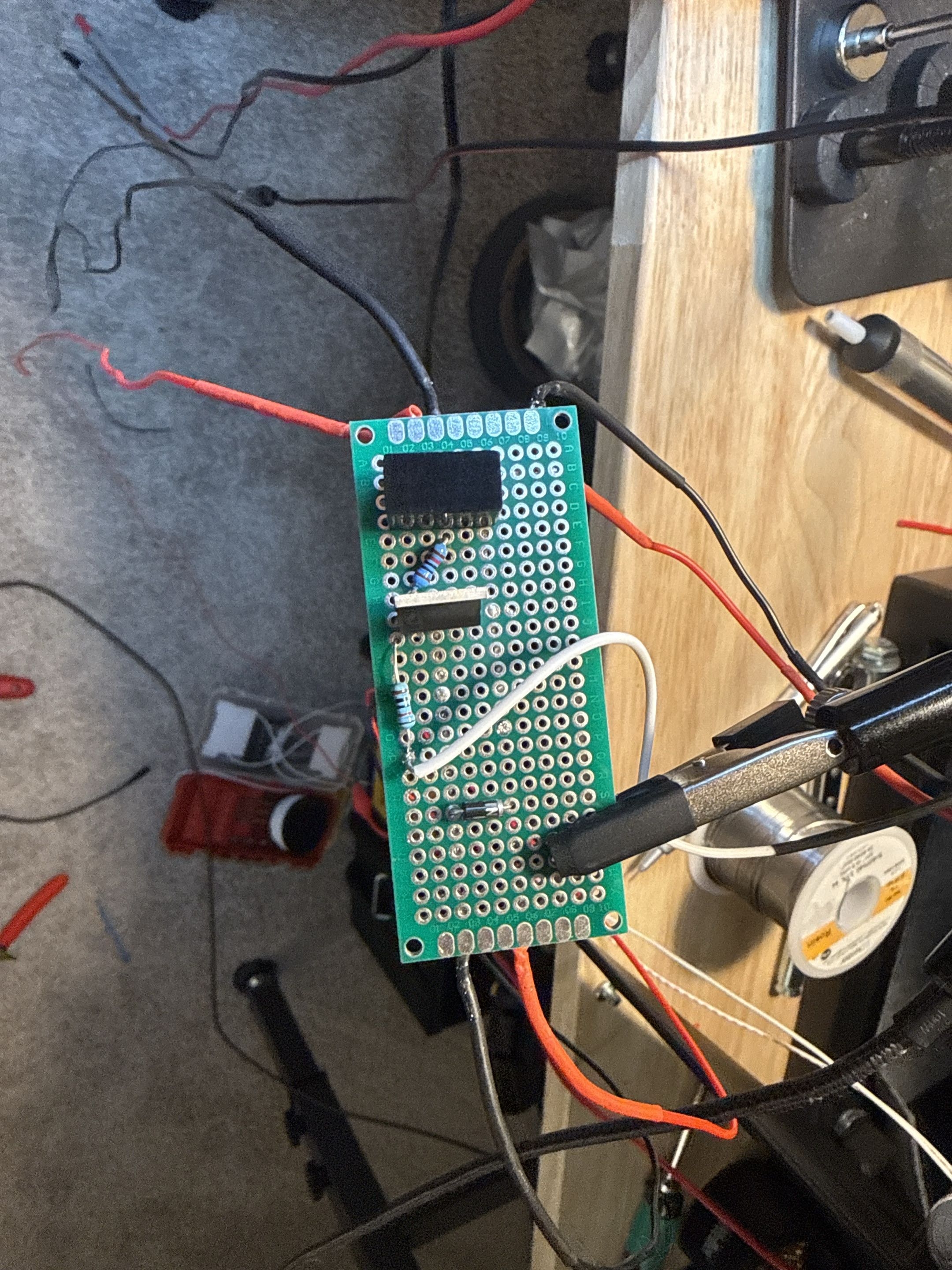
Control-board prototype

Control-board prototype

Top side of the perfboard control circuit used for the MOSFET-switched solenoid path and support components.

Build evidence

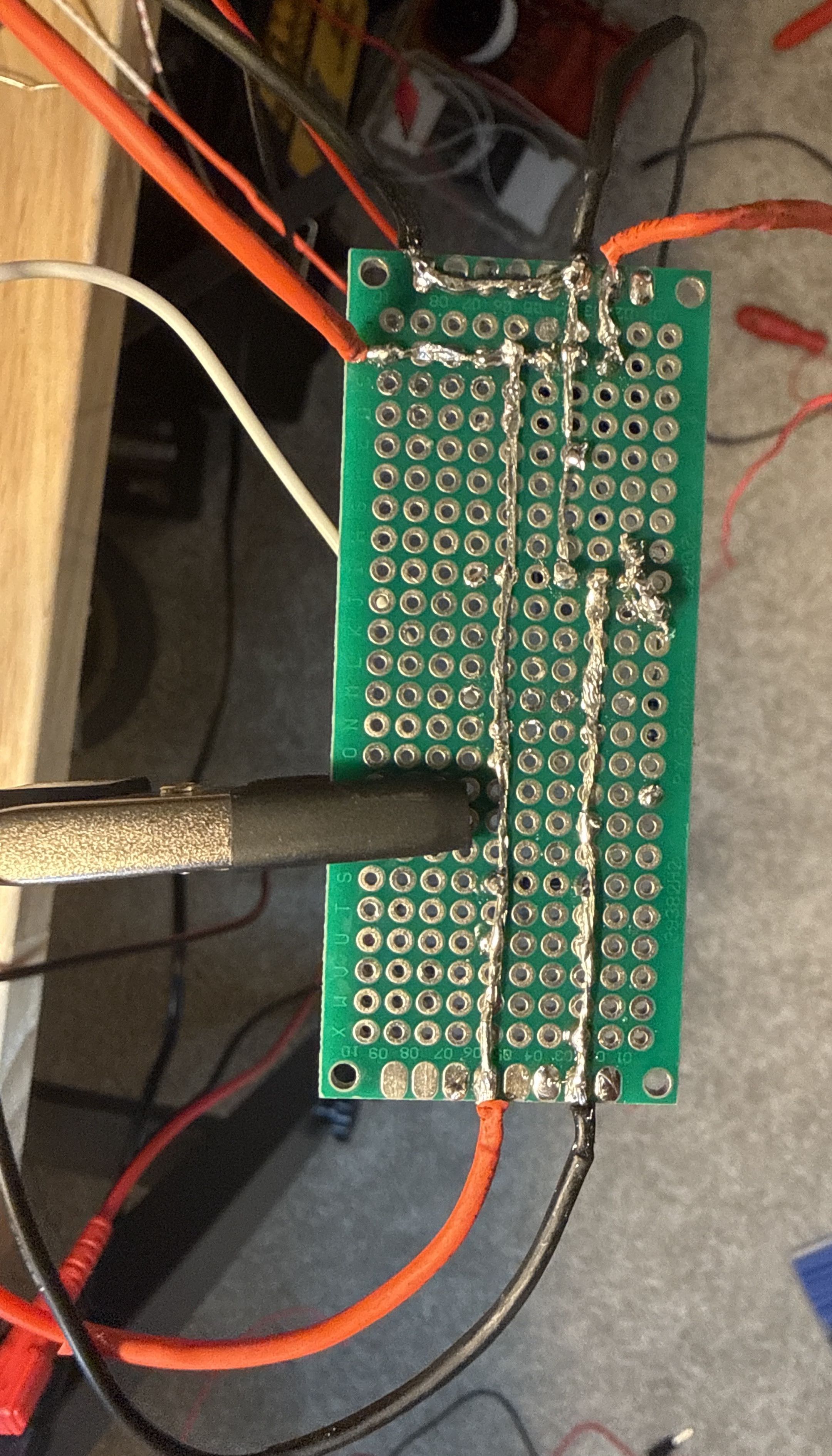
Underside wiring and solder rework

Underside wiring and solder rework

Back side of the perfboard during debugging. This was part of the learning and rework process, not a polished production PCB.

Build evidence

Solenoid latch mechanism

Solenoid latch mechanism

The latch mechanism removed from the safe door so the actuator behavior could be understood directly.

Build evidence

Back to work Contact