Drones

Custom FPV Quadcopter

Built a custom FPV drone from individual parts instead of using a ready-to-fly kit. I wired the power path, flight controller, ESC, motors, and ELRS receiver, brought it up in Betaflight, and completed initial flight testing.

Flown, tuning needed FPV Betaflight ELRS Soldering ESC Hardware bring-up
Custom FPV Quadcopter
Built from individual components
ELRS + Betaflight configured
Initial flight test completed

Overview

Project Summary

A custom FPV drone build focused on wiring, power validation, receiver setup, Betaflight configuration, motor testing, flight testing, and hardware troubleshooting.

What I built

I built a custom FPV quadcopter from individual components instead of starting with a ready-to-fly kit. The build included the frame, motors, ESC, flight controller, receiver, power path, capacitor, transmitter link, Betaflight setup, bench motor testing, and initial flight testing.

Why I built it

This was my first real robotics-adjacent project. I wanted something that would actually challenge me, so instead of starting with a basic robot car or claw kit, I chose a drone. That made the project harder because the wiring, firmware, controller link, power system, and tuning all had to work together before it could fly.

System

Core Hardware

Flight controller Holybro Kakute H7 v1.3
ESC Holybro Tekko32 F4 4-in-1 ESC
Receiver HGLRC Hermes 2.4 GHz ELRS
Transmitter RadioMaster Boxer ELRS
Power 4S LiPo, XT60 pigtail, capacitor
Safety ViFly Short Saver 2
Video DJI Goggles 2, DJI O4 Air Unit, analog fallback hardware

Build process

What I Personally Did

Selected and assembled the main hardware stack
Wired the ESC, flight controller, receiver, XT60 pigtail, capacitor, and motor path
Checked continuity before applying battery power
Used a short-saver during first power-on
Configured Betaflight ports and receiver settings
Bound the ELRS receiver and validated receiver input
Tested motor output from the Betaflight Motors tab
Debugged UART, receiver, arming, and ESC behavior
Troubleshot an early controller / receiver pairing blocker before switching to a RadioMaster Boxer ELRS
Identified the DJI O4 compatibility issue with the selected stack
Completed initial flight testing and confirmed the drone could lift off and fly

Problems I ran into

The first major blocker was the controller and receiver link. I started with a BETAFPV LiteRadio 2 SE ELRS V3 and ran into pairing, firmware, and flashing issues. I tried multiple software and hardware-level troubleshooting paths, including bootloader / flashing attempts, but the reliable fix was moving to a RadioMaster Boxer ELRS and reworking the control-link setup from there.

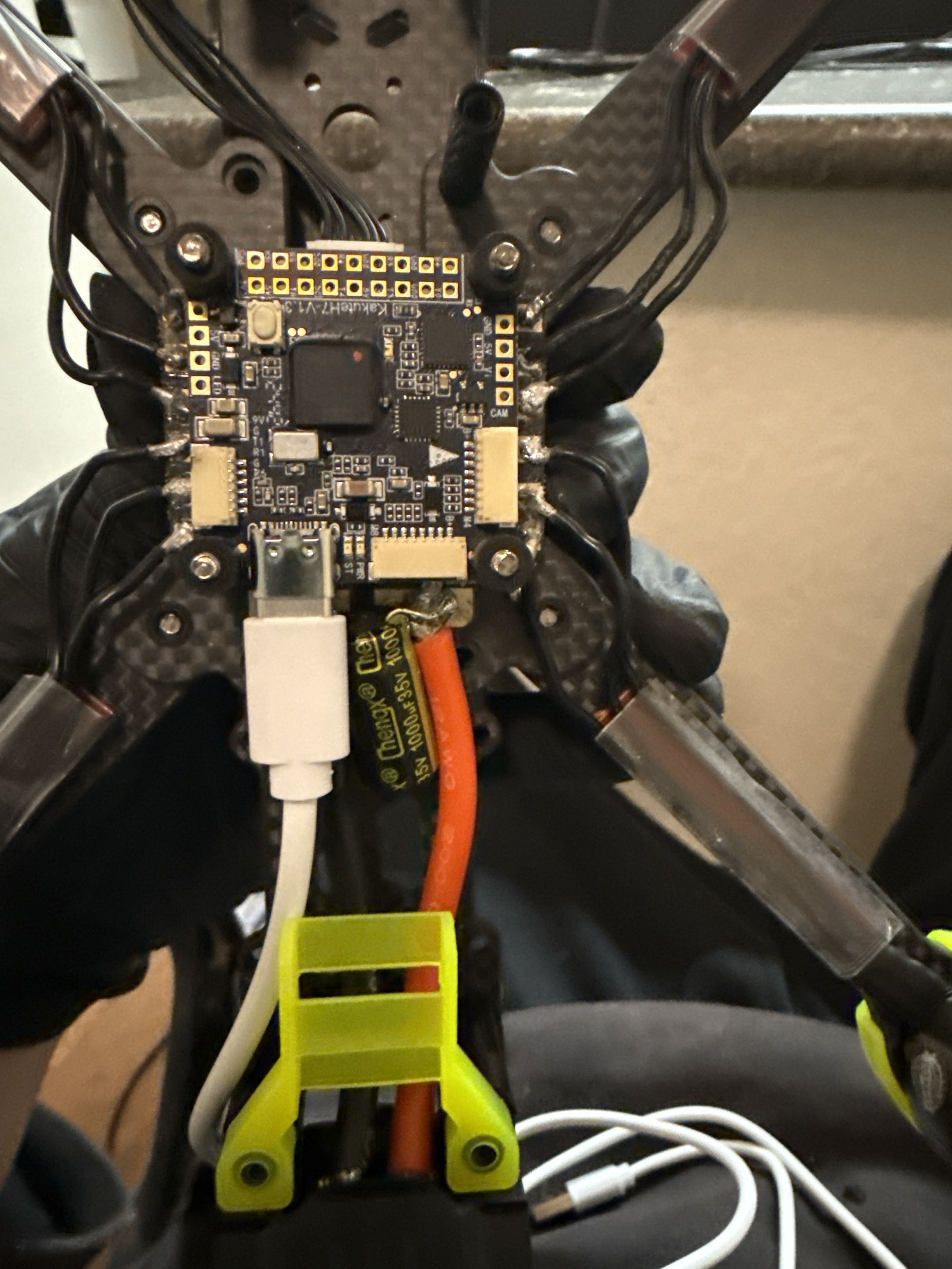
The receiver did not immediately behave as expected in Betaflight. The issue was not only power or binding; the UART and serial receiver configuration also had to line up before Betaflight could see valid receiver input.

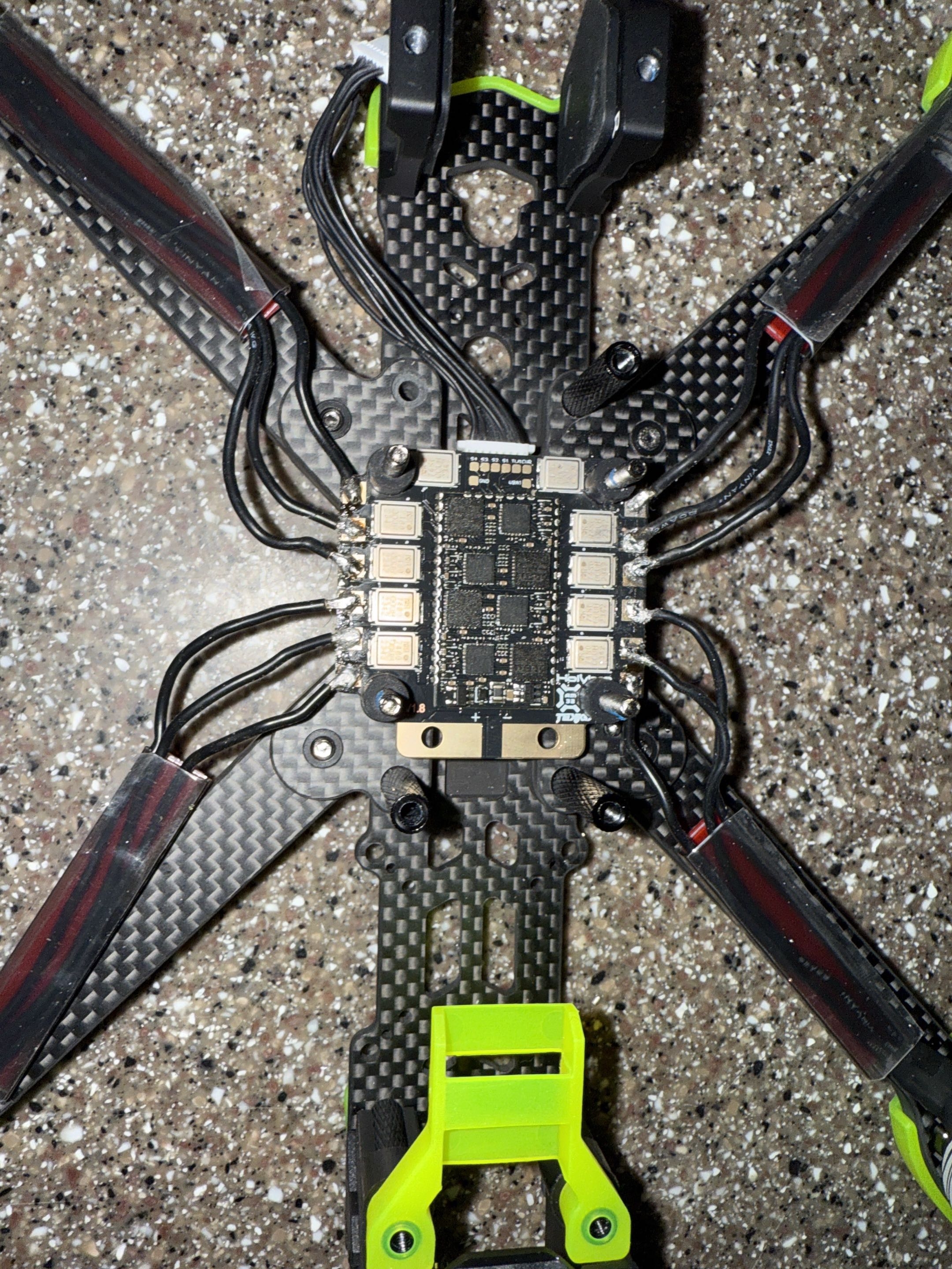
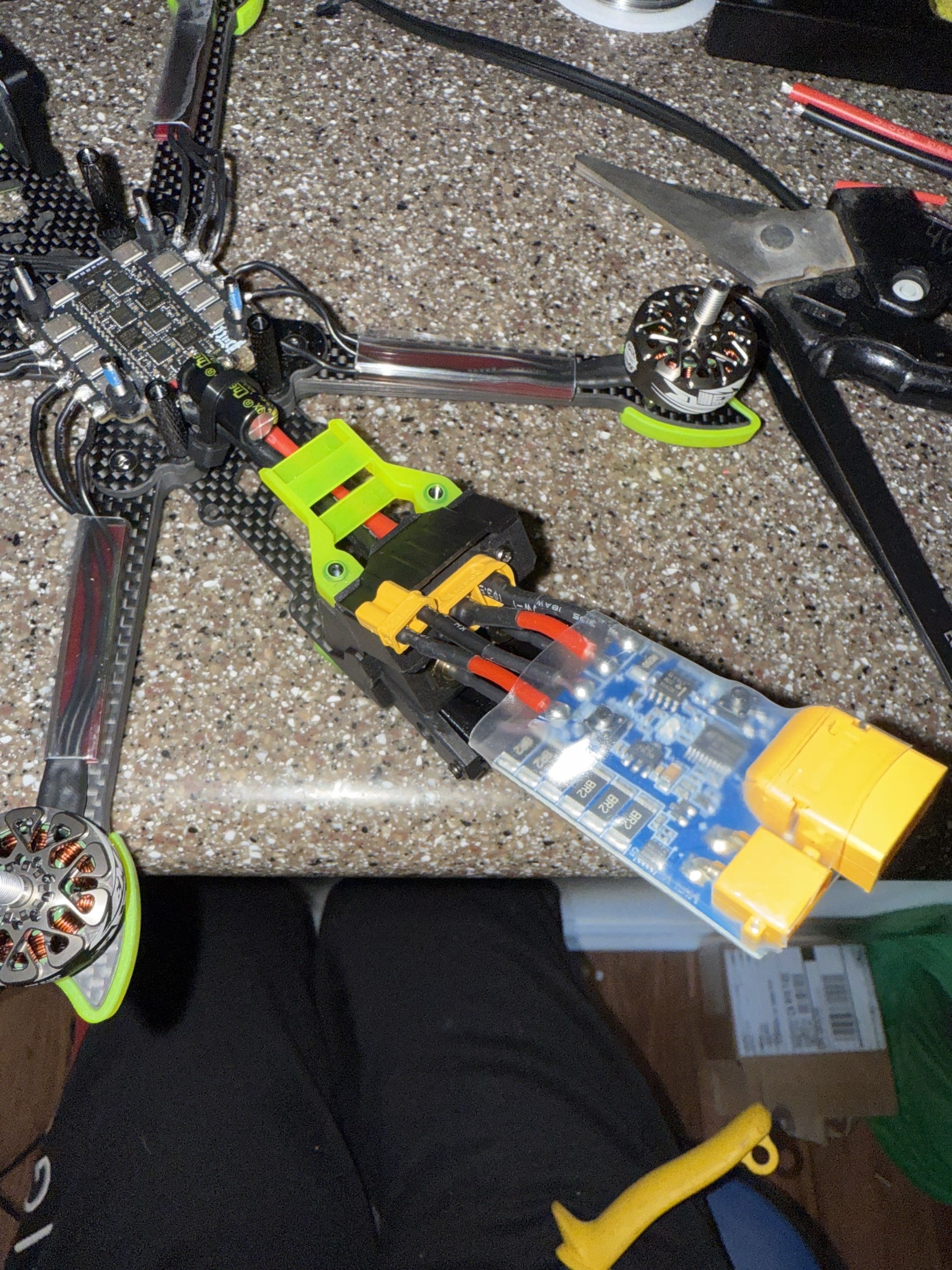
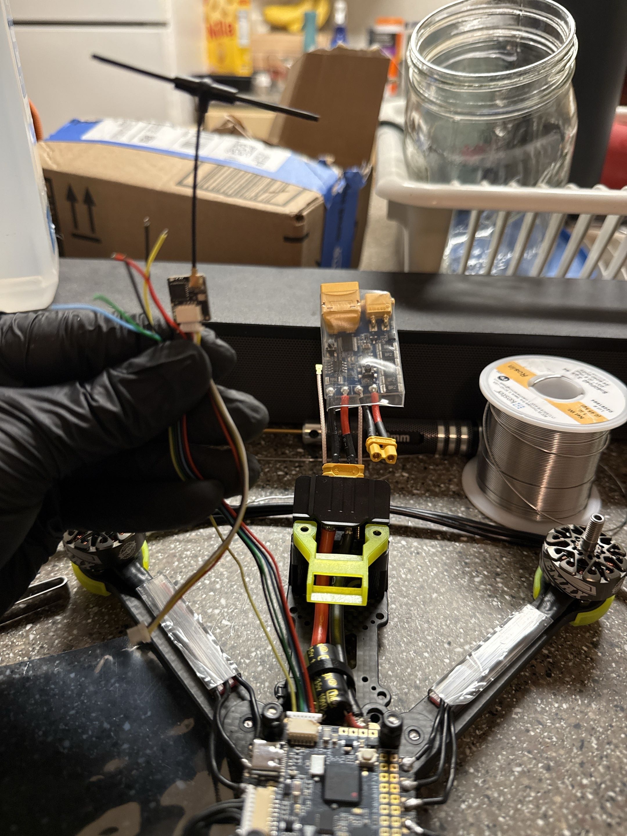
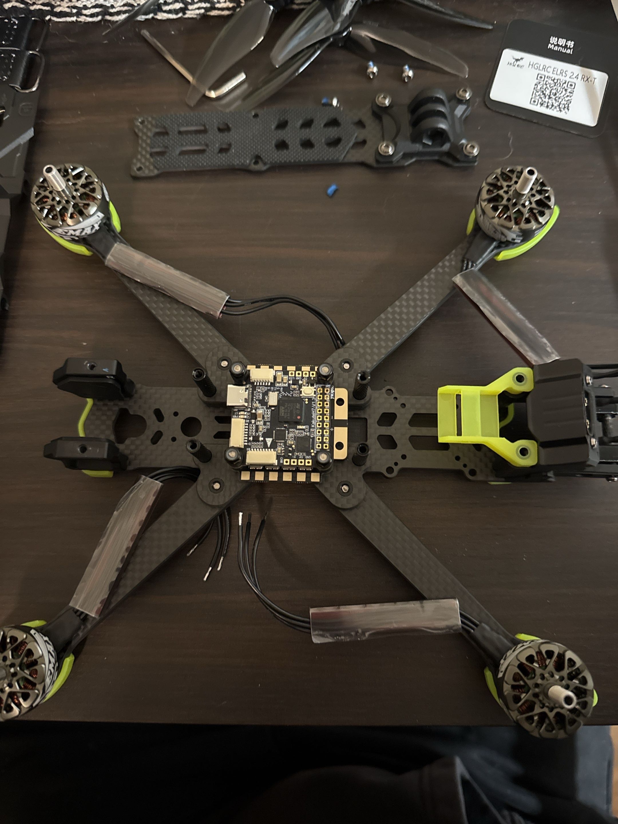
The build exposed arming blockers and ESC telemetry limitations. Motors eventually spun during bench testing, but the ESC telemetry / BLHeli32 path was not cleanly resolved.

The DJI O4 Air Unit exposed a compatibility issue. I bought it for the digital video path, but the flight-controller and video stack I chose were not a clean match. I documented it as hardware I owned, not hardware that was fully integrated into the working build.

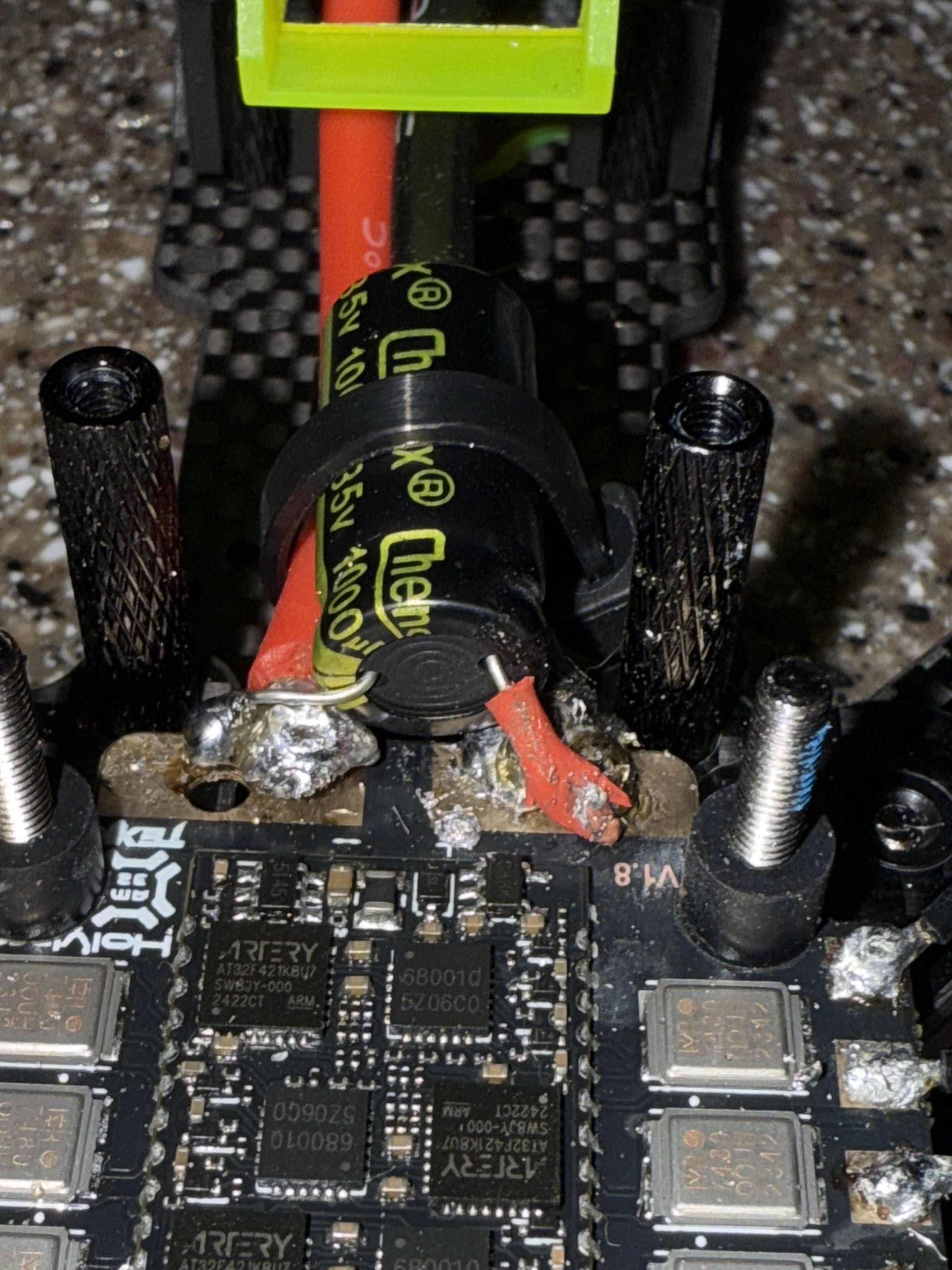
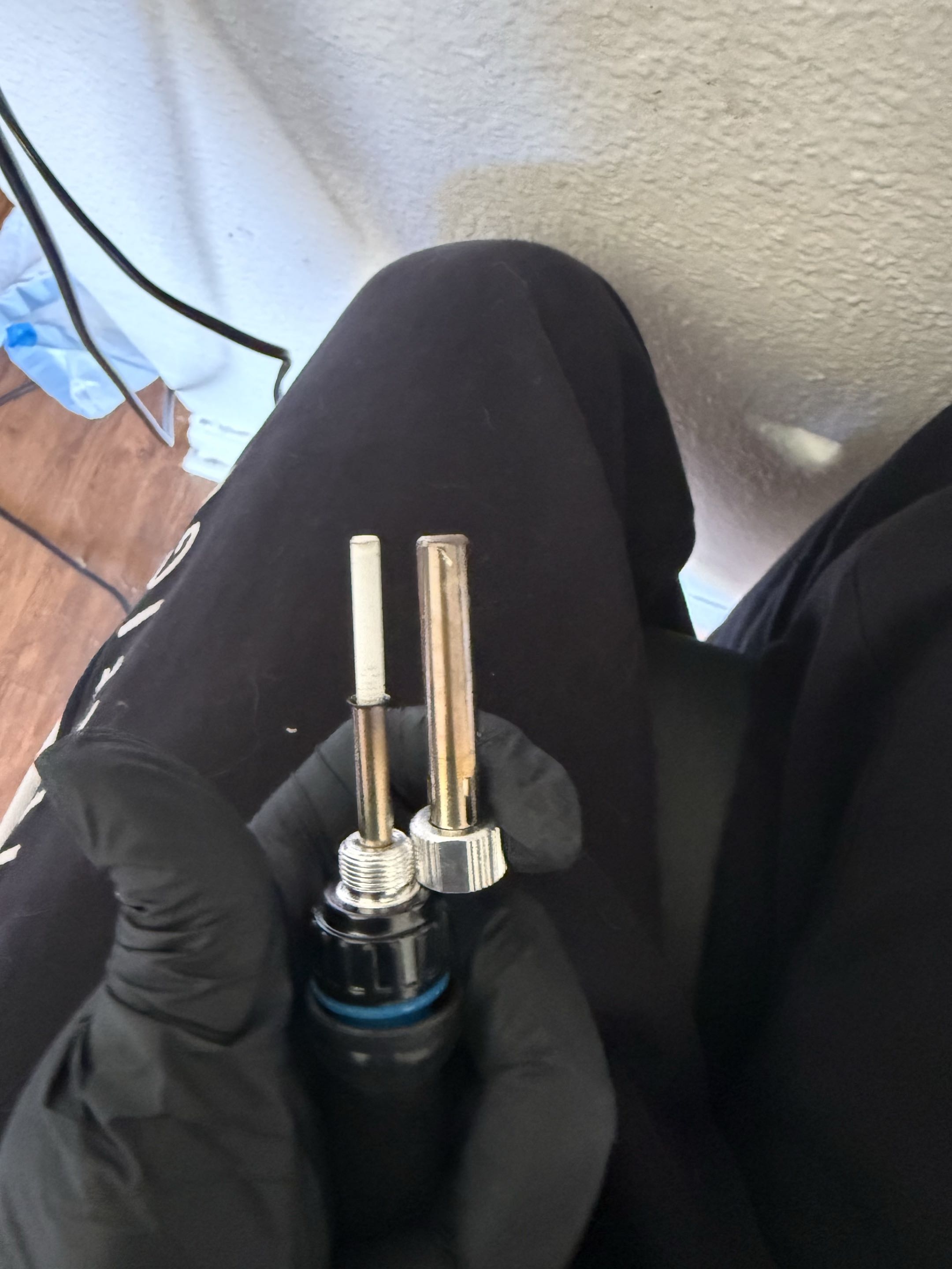
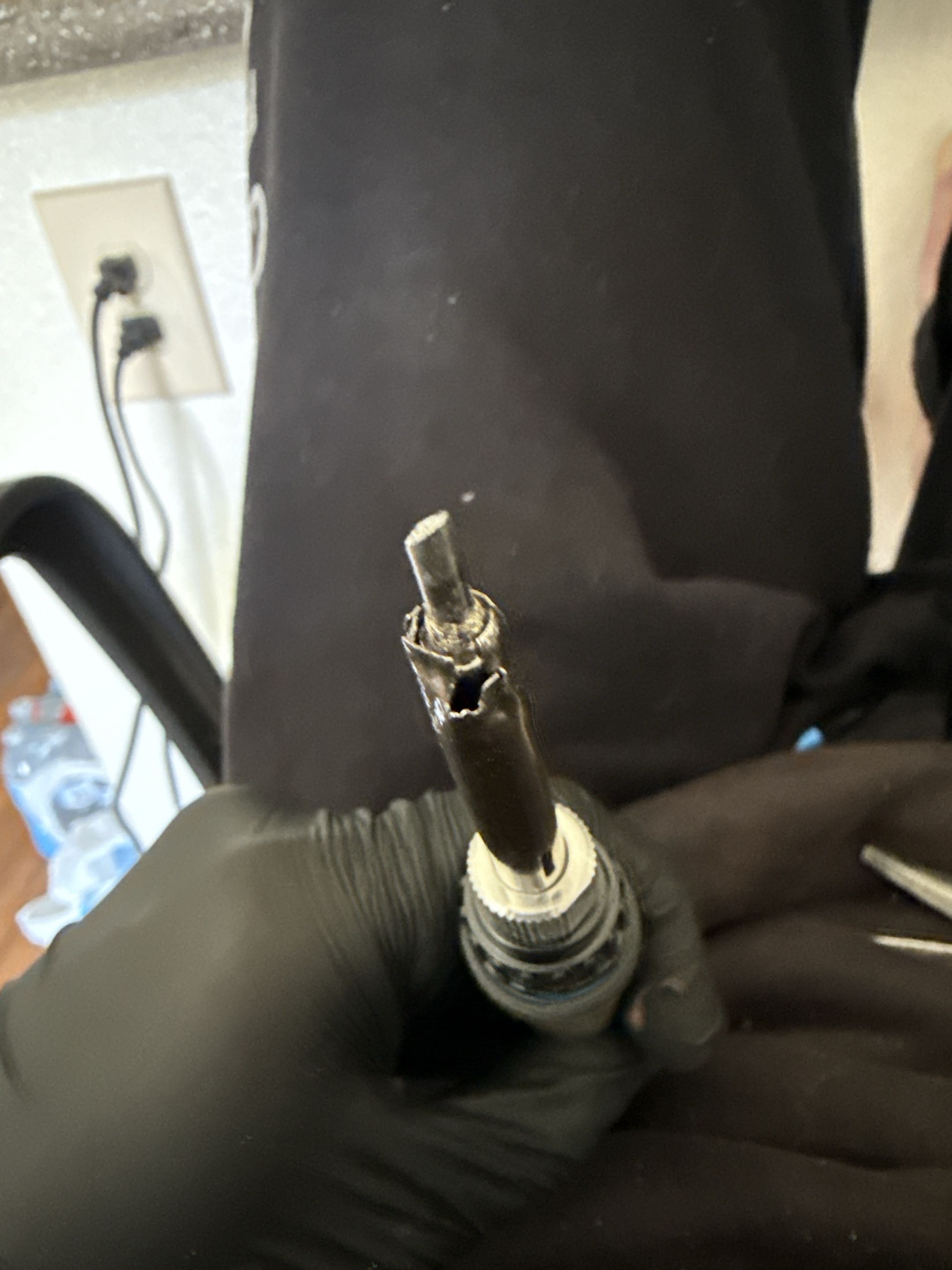
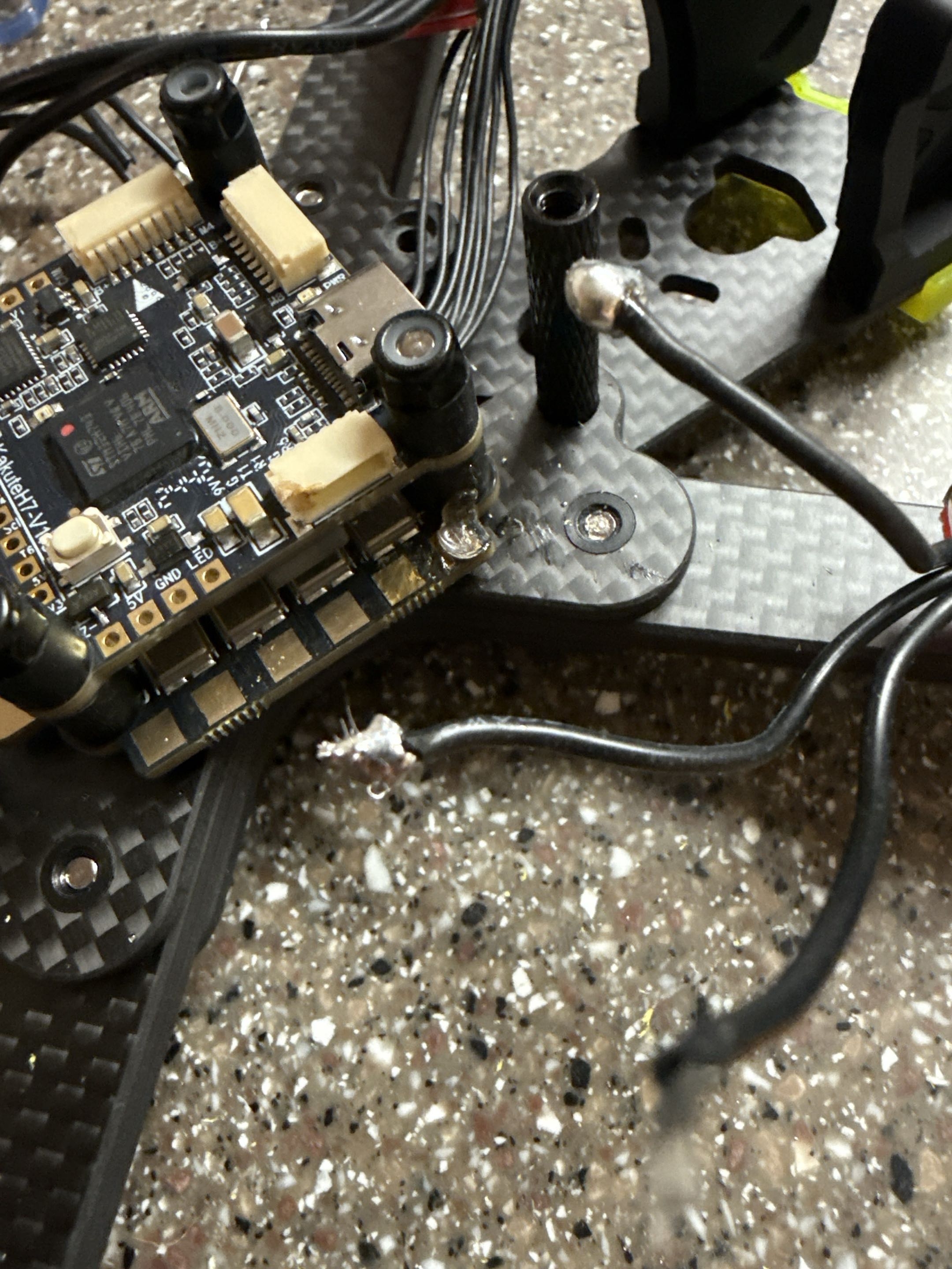
The soldering process was affected by a tool issue: the soldering iron tip was not making reliable thermal contact. I made a temporary crimped contact repair so I could keep working while waiting on better equipment. The current soldering is documented honestly and planned for rework.

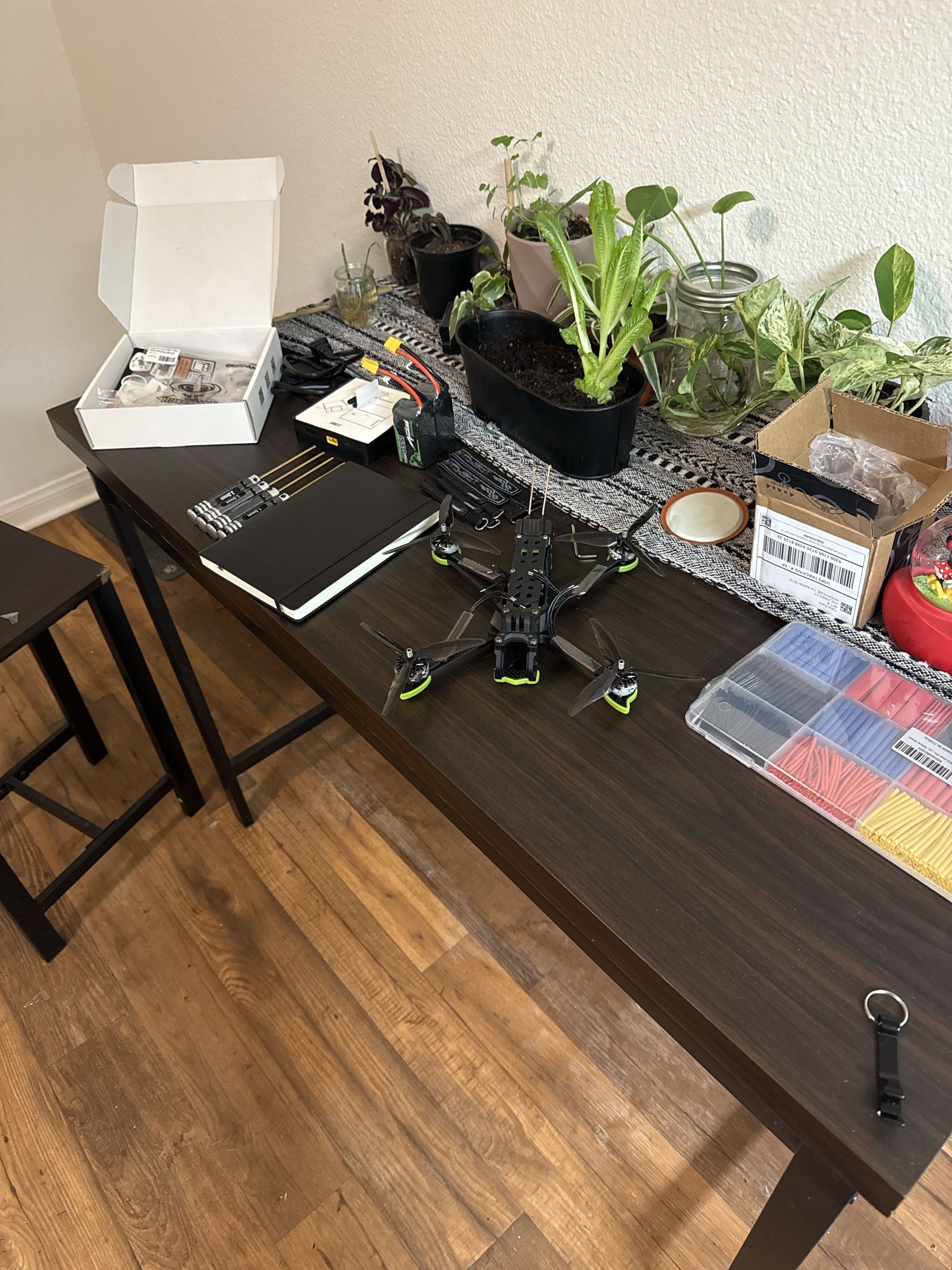
The drone did fly, but it was too sensitive for my skill level at the time. The airframe had more power than I was comfortable controlling, so the next step is tuning and controlled flight practice rather than claiming it as a polished aircraft.

What worked

  • • Safe first power-on process
  • • ESC-to-flight-controller wiring validation
  • • ELRS receiver bind with the RadioMaster Boxer
  • • Receiver data visible in Betaflight
  • • Betaflight configuration and motor testing
  • • Motors spinning during bench tests
  • • Initial flight test completed
  • • Basic staged hardware bring-up workflow

Remaining work

  • • PID / rate tuning for more controllable flight
  • • Final video path
  • • Exact frame, motor, prop, capacitor, and battery specs
  • • Betaflight config export
  • • Cleaner final build photos
  • • Reworked soldering with current tools and current skill level
  • • Longer controlled flight testing

Takeaway

What I Learned

This project made me better at staged hardware bring-up. I learned to test power first, then receiver input, then motor output, instead of trying to make the whole drone work at once. It also taught me that a robotics system can fail at several layers: hardware, firmware, radio link, software configuration, power delivery, or tuning. The drone eventually flew, but the control sensitivity showed me that getting a system airborne is not the same thing as having it tuned, documented, and easy to operate.

Evidence

Build Gallery

Frame and flight controller layout

Frame and flight controller layout

Early layout stage with the carbon frame, motors, arms, and flight controller positioned before the system was fully closed up.

ESC and motor wiring

ESC and motor wiring

Motor leads soldered to the 4-in-1 ESC and routed through the frame during the main wiring stage.

Power path and capacitor

Power path and capacitor

XT60 power lead and capacitor installed as part of the main battery power path.

Short-saver power test

Short-saver power test

Safe first-power setup using a short-saver before applying full battery power directly to the build.

Flight controller configuration stage

Flight controller configuration stage

Flight controller installed and connected over USB for Betaflight configuration and bring-up testing.

Receiver bring-up

Receiver bring-up

ELRS receiver and wiring staged during receiver binding, UART setup, and system integration.

Build workspace

Build workspace

Workbench context showing the drone, tools, parts, and supporting hardware during the build process.

Soldering iron contact issue

Soldering iron contact issue

The soldering iron tip was not making reliable thermal contact, which made soldering harder than it should have been.

Temporary tool repair

Temporary tool repair

Temporary crimped contact repair used to restore enough heat transfer to continue work while waiting on better equipment.

Constraint during soldering

Constraint during soldering

Example of the rougher soldering conditions caused by the tool contact issue. This is planned for rework with better equipment.

Back to work Contact